DNA DISCRETE NETWORK ASSEMBLY
SHAJAY BHOOSHAN STUDIO PHILIPP SIEDLER FEDERICO BORELLO BEGUM AYDINOGLU
DRL 2015/2017 ARCHITECTURAL ASSOCIATION
STUDIO BRIEF INTRODUCTION
Shajay Bhooshan’s Studio-Brief is suggesting to revisit Le Corbusier’s Maison Domino. The “Domino House” was designed for building mass production in 1914, during the housing crisis after World War One. It was seen as a prototipycal diagram for contemporary manufacturing and assembly in architecture. Le Corbusier is distilling the essential elements of a building in the most minimal manner: columns and circulation feeding to the open plan slabs. Le Corbusier’s solution for the housing crisis, Maison Domino, is a standardized two story building which had no walls or defined rooms, but a structural skeleton. The structural skeleton is consisting of three slabs supported by six load bearing columns on each story and a staircase, all casted in concrete. The word “Domino” comes from “domus” and “innovation”. It is also referring to the modularity of the dominoes of the similar named board game, as the houses that can be joined from end to end. This modularity was key for the application of the mass produced housing units. Le Corbusier wanted to patent the idea of Maison Domino, with his partner Max Du Bois who owns a concrete company. The idea was an assembly line of houses, like Henry Ford invented for the automobile industry. Eventually, due to lack of backers, Le Corbusier abandoned the patenting and construction idea. Thus the diagram remained in the architectural environment and is used all over the world as a role model. We are revisiting the Domino House by extracting the key concepts of the diagram, critically rethinking solutions bearing in mind contemporary technology and social knowledge. Consequently, the use of industrial robots, as a tool for manufacturing and design is suggested. The design and distribution process is the focus of the project, while the robot with its constraints is a main driver, informing the designer in a close feedback-loop.
ABSTRACT INTRODUCTION This thesis document criticizes current manufacturing processes heavily depending on complex temporary formwork and scaffolding, proposing an integration method of scaffolding as an actuated permanent equal member of the building structure.
Rethinking Scaffolding. Recent rapid development of computer aided design (CAD) tools and computers give designers and architects possibilities to design and simulate complex geometries and building structures. Constructing this shapes require increasing complex formwork and scaffolding (Image 1. building site Pantheon, Rome), temporary structures to support and hold building elements in place, removed and most likely wasted after building completion1. Image 1. Construction site of the Pantheon in Rome built by Apollodorus of Damascus in about 126 AD.
Lightweight Structure2. A revisited building sequence also influences and initiates space to rethink the building structure itself. Lightweight structures are of interest for ages. From Antoni Gaudí’s Sagrada Familia, and his hanging chain models to Frei Otto’s tensile tent structures (Image 2. Munich Olympia Stadium, Frei Otto), emphasizing smallest amounts of material used while maintaining performative properties. Image 2. Munich Olympic Stadium, Frei Otto and Gunther Behnisch, built in Munich in 1972.
Geometric Importance. Current development in digital fabrication methods and growing accessibility by all professions open up new opportunities for architecture in the 21st century. Rapid digital simulation helps us to calculate physical phenomena and predict possible outcome more precise and fast than ever. Advanced geometric thinking becomes increasingly valuable3, especially for economic reasons. Through tools in the genre of computer aided manufacturing (CAM) the gap between advanced geometry in the digital and fabrication in the real world becomes smaller (Image 3.Palazzetto dello Sport, Pier Luigi Nervi). Image 3. Palazzetto dello Sport, Pier Luigi Nervi, built in Piazza Apollodoro in 1957.
The approach to be presented suggests a topology optimisation process4 with the objective of material reduction. A compression tension algorithm defines positioning of segmented members5 of an integrated spatial network, actuated by a membrane wrapping strategy, replacing conventional formwork and scaffolding, as part of the light weight building structure. 1According to a study from 2011, 80% of the total waste production is created in the construction industry ,of which 1.97% comes from the formwork timber. 2Frei Otto, Lightweigth Principle, Institut für leichte Flächentragwerke (IL), 1998. 3Corentin Fivet and Denis Zastavni, Robert Maillart’s Key Methods from the Salginatobel Bridge Design Process, Journal of the International Association for Shell and Spatial Structures, 2011. 4Bendsoe MP, Sigmund O, Topology optimization: theory, methods and applications. Springer, Berlin, 2002. 5Bendsoe MP, Optimal shape design as a material distribution problem. Struct Optim 1(4):193–202, 1989.
THESIS STATEMENT INTRODUCTION
The project engages topology optimisation1 in architecture, with the objective of material reduction in building structure, while maintaining performative properties. In the automotive and aeronautic industry, optimisation processes to economize weight and resources are common practice and vital for flying and driving performances. Comparing a tower building and a cars structural elements performance per cubic meter, the building element is exposed to a multitude of stress and at the same time vastly underdeveloped. More money, resources and waste capacity are spent for building construction than anything else in the world, yet nowadays old fashioned building regulations and code tables of isotropic building structure profiles are used and planned with. Topology optimisation (TO) processes for material distribution describe the location of material, but give no manufacturing information. While TO assumes an equal distribution of material mass we suggest to substitute solidity of profile with an advanced geometric approach. A spatial network of straight segments constructed as an inner scaffold enabling wrapping of the outer membrane2. Skeleton and membrane work together as equal performing members of a hybrid structural system. The approach suggests to initially keep the purpose of scaffolding, but further in the building sequence, integrates it as a vital member of a hybrid structural system. Instead of constructing a complex temporary scaffold, which after building completion will be removed and possibly wasted, this approach suggests to integrate scaffolding as an equally important member of the building structure. A scaffold not supporting from the outside, like concrete formwork, but spatially independent, growing in any possible way, inside as the structural backbone. This also gives the designer and architect ultimate freedom in construction, able to design an uninterrupted continuously flowing space defining structural surface. The skeleton and membrane system only works by combination in order to reach a state of load bearing equilibrium between the two members. The skeleton is constructed by a spatial network from discrete elements with circular profiles. Their thickness is relative to the tension and number of layers of the membrane. A strong node but with flexible segment allows for bending tolerance and gives the system the ability to act like a tensegrity system. Integrating tension by wrapping the flexible inner skeleton, gives the structure strength and stiffness in its final stage.
MULTI ROBOTIC ASSEMBLY PLA / LDPE HYBRID SYSTEM SELF SUPPORTING NETWORK+MEMBRANE

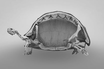
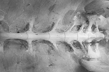
1Bendsoe MP, Sigmund O, Topology optimization: theory, methods and applications. Springer, Berlin, 2002.

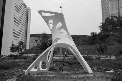
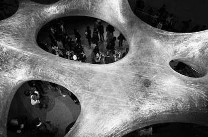
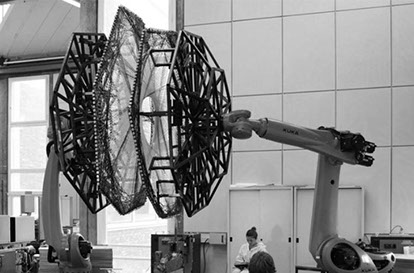
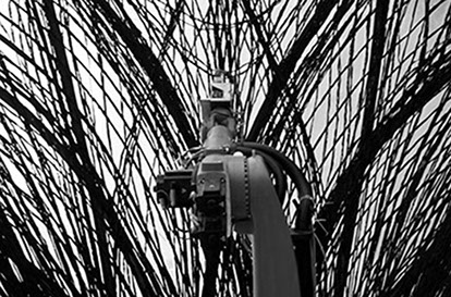
2Achim Menghes, Robotic woven pavillion, ICD / ITKE Stuttgart, 2015

MAIN REFERENCES INTRODUCTION
Several case studies have been considered to have a better understanding of how to locate the project in the cultural and technological framework of the studio agenda. References from the natural, professional and academic world have been explored in order to identify a coherent approach from digital exploration and conceptualisation to the materialisation of the project. Background research plays a crucial role to identify what already has been done in the field and to inherit knowledge from it, in order to push the research project to a further level of depth and complexity. Materialising Topology Optimisation: Membrane
 Topology optimized concrete shell HyperTHREADS 2013, Mexico  Trees cocooned in webs after flood in Pakistan Russel Watkins
 Spatial wrapping Numen  Trees cocooned in webs after flood in Pakistan Russel Watkins
 Materialising Topology Optimisation: FRAME
 Turtle shell structure Natural History Museum, London  Turtle spine structure Natural History Museum, London
 Submarine hull structure Bill Wilson  Topology optimised chair Zaha Hadid Architects (CODE)
 Robotic Fabrication
 Complex timber structures Gramazio Kohler Research, ETH Zurich 2012-2017  Design and assembly of lightweight metal structures Gramazio Kohler Research, ETH Zurich 2014-2018
 Robotic weaving ICD / ITKE Stuttgart 2015  Fiber reinforcement ICD / ITKE Stuttgart 2014
Architectural Context INTRODUCTION
DOMINO HOUSE The “Domino House” is a housing diagram designed by architect Le Corbuiser, as a soulution to unavoidable housing shortage after World War One. The world “domino” comes from “domus” and “innovation”. It is also referring to the modularity of the dominoes of the similar named board game, as the houses that can be joined from end to end. Prefabricated reinforced concrete was the material for the frame which also could be assembled by non-professionals. Later, Le Corbusier wanted to patent the idea of Maison Domino, with his partner Max Du Bois who owns a concrete company. The idea was an assembly line of houses, like Henry Ford invented for the automobile industry. Eventually, due to lack of backers, Le Corbusier abandoned the patenting and construction idea. Thus, the diagram remained in the architectural environment and is used all over the world as a role model. The principles of maison domino1 can be observed in following Le Corbusier buildings such as Villa Savoye and Unite d’habitation. The genericness and adaptability of Domino System made it still effective beyond the industrial age. Other than being a positive quality, flexibility-adabtibility became a fundamental ‘mechanism’ for social engineering of spontaneous settlements like Brazilian ‘favelas’ (Image 5) or Greek ‘polykatoikias’ (Image 6 ) which were as a multi-storey apartment building for the Athenian bourgeoisie2. (Vittorio Aureli, Issaias and Giudici, 2012) In this thesis, we are revisiting the Domino House by extracting the key concepts of the diagram, critically rethinking solutions bearing in mind contemporary technology and social knowledge. 1Le Corbusier, and Etchells, F., Towards a new architecture. London: Architectural Press., 1946 2Vittorio Aureli, P., Issaias, P. and Giudici, M., From Dom-ino to Polykatoikia. Domus, 2012
 Image 5. Pre-fabricated Housing Structure in Heliopolis Favela, Sao Paulo (Brazil)
 Image 6. ‘Polykatoikias’ in Athens(Greece).
The Maison Domino has key points that Le Corbusier had declared in his 5 points of architecture1. These principals can also be observed in Le Corbusier’s other housing projects such as Villa Savoye and Unite d’habitation. _1 Columns(Pilotis) Elevating the mass off the ground _2 Free Plan (Plan Libre) Seperation of the load bearing columns from the walls that subdivides the space. _3 Free facade (Façade Libre) Continuation of free plan in vertical plane _4 Ribbon Window (Fenetre de Longerue) Long horizontal sliding window _5 Roof Garden (Toit-Jardin) Restoring the area of ground covered by the house
 Image 18. Villa Savoye, Le Corbusier, 1931
 Image 19. Unite d’habitation, Le Corbusier,1952
The construction system of Maison Domino is designed to minimize the use of material reducing the global weight and cost, to counter the housing demand after the 1914 where one fifth of the Belgian population was homeless. It would have been as an house factory line, like Henry Ford invented one year before for the aumobile industry. The architectural elements of the Domino diagram reflect Le Corbusier’s five points previuosly mentioned. The pilotis allows to free the facade of the structural function and open up the plan to a more free interpretation without the constraint of structural walls. The staircase is positioned on the side of the module to allow the repetibililty of the latter, both in the horizontal and vertical axis. The innovative elements introduced by Le Corbusier were possible thanks to the use of concrete as material for the entire structure, pilotis, slabs and staircase1. Le Corbusier had Fordist standardisation in mind and yet produced the perfect architectural symbol for an era obsessed with customisation and participation. Stripped of architecture, the Dom-ino is pure system. It is an invitation to complete it in anyway people prefer.
2.55 m 2.55 m 0.3 m 0.3 m 0.3
4.1 m 4.1 m 2.4 m
4.1 m
The Domino House diagram has been criticised according three main aspects: _1 Material Isotropic distribution of the concrete, resulting in structural redundancy. _2 Grid System Rigid grid system which doesn’t allow program flexibility and adaptable configuration. _3 Surface Absence of surface / enclosure strategy.
Material Topology Optimisation (material redistribution)
Programatic Adaptability Flexible layout
Introducing Surface Hybrid system (structure + surface)
TECHNOLOGICAL Context INTRODUCTION
ROBOTIC FABRICATION IN ARCHITECTURE In 1990s, with the impact of increasing use of digital technologies in architecture, abstract virtual worlds came into the architectural scene. Those digital worlds without materiality is exploring the limits of architecture through computer aided design technologies. Introduction of computer controlled processing machines such as milling and laser cutting gave materiality to the abstract dematerialized virtual world. As the modernist efforts reformulated the transformation of architectural production into a fully automated and rationalized industry, robotic fabrication in architecture became relevant. With the use of robotic technology in architecture, digital technologies are no longer constrained to design, it also becomes practicable for construction. Merging of previously independent domains, robotic technology and materialist actuality of architecture, distinguishes construction automation and general robotisation1. Robotic fabrication in architecture expanded a new dialogue between design and making, as it leads to high resolution, precision and customisation. Additionally, it is taking advantage of real-time data flow between design and production by using feedback mechanisms. The term “Digital Materiality in Architecture”2, (Digital materiality in architecture, 2008), sharpened its meaning as the robotic fabrication expands the capacity of the digital world. The very first architectural application of an industrial robot was in 2006, Gantenbein Vineyard Façade in Switzerland (Image 20). Robotic production that ETH developed enabled to lay 20,000 bricks precisely on the desired angle and prescribed intervals. 72 elements which were robotically prefabricated were regularly transported and locally assembled. (Image 21). 1 Fabio Gramazio and Matthias Kohler, The Robotic Touch: How Robots Change Architecture, Research ETH Zurich 2005-2013. 2 Fabio Gramazio and Matthias Kohler, Digital materiality in architecture. Baden: Lars Müller Publishers, 2008.
 Image 20. Gantenbein Vineyard Façade, Gramazio & Kohler, Switzerland, 2006
 Image 21. Gantenbein Vineyard Façade Fabrication, Gramazio & Kohler, Switzerland, 2006
 Image 22. Complex timber structures Gramazio Kohler Research, ETH Zurich 2012-2017
ADDITIVE MANUFACTURING In terms of manufacturing technology that could be implemented in robotic fabrication, there are additive (ΔM1>0), substractive (ΔM<0), and formative techniques (ΔM = 0), (Chua,Leongi & Lim, 2010). In the subtractive manufacturing processes, raw material, often up to 95 per cent, is removed to achieve the finished component.2 On the contrary, additive processes only uses the material they need to make the part. The history of additive manufacturing (Image 23) is relatively short in comparison with equivalent and subtractive (Image 24) manufacturing. In 1983, the first prototype of a stereolithography (SLA) machine for 3D printing was created by Chuck Hull. Additive fabrication allows complex and performative components out of basic materials. It allows for material customisation and manipulation of the geometry during the fabrication. This adds additional degree of freedom to the process. Binder jetting A liquid bonding agent is selectively deposited to join the powder materials. Directed energy deposition Focused thermal energy, such as laser, is used to fuse materials by melting as the material are being deposited to form an object. Material extrusion Materials are heated and selectively dispensed through a nozzle. Material jetting Materials, such as photopolymers or wax, are selectively dispensed through a nozzle. Powder bed fusion Thermal energy selectively fuses regions of a powder bed. Sheet lamination Sheets of materials are cut and stacked to form an objects. Vat photopolymerization The use of certain types of light, such as ultraviolet light, to selectively solidify liquid photopolymers*. *Photopolymer: A light-sensitive polymeric material, especially one used in printing plates or microfilms. Source: GAO analysis of ASTM international data.
 Image 23. Additive Robotic Fabrication of Complex Timber Structures, Zurich, 2012-2017.
 Image 24. Subtractive Robotic Fabrication, Hot Wire Cutting. Odico Formworks, Denmark
 Image 25. Design and assembly of lightweight metal structures Gramazio Kohler Research, ETH Zurich 2014-2018